Optimising STANAG 5066 Parameter Settings for HF and WBHF
When using STANAG 5066 to communicate over HF Radio and Wide Band HF (WBHF), transmit speed and other parameters can be modified to optimize performance. This paper describes ongoing Isode research on possible new approaches to give better performance for traditional and modern applications.
This paper looks at STANAG 5066 Data Rate Change approaches in current use and deficiencies of the current state of the art. The paper then analyses HF and WBHF characteristics, to help consider how the identified problems may be addressed.
Finally, the paper proposes new STANAG 5066 Messages that can be used to implement the proposed changes and enable further research. We anticipate that this work will lead to input on future standardization work.
Groundwave and Skywave
HF has two distinct modes of transmission: Skywave and Groundwave. Much HF research and literature is focused on Skywave as many of the difficult technical problems of HF relate to Skywave.
Both modes of operation are significant operational importance. In particular, Groundwave is extensively used for naval communications as Groundwave works well over water and enables communications over hundreds of nautical miles.
When simulating channels, AWGN (Additive White Gaussian Noise) is generally considered a good model for Groundwave, whereas the CCIR models are appropriate for Skywave. Intermediate Term Variation (ITV) is an important Skywave characteristic but does not significantly affect Groundwave.
This paper makes some clear conclusions for Groundwave, while identifying the need for further research on ITV in support of Skywave. It seems quite likely that it will be optimal to use different algorithms for STANAG 5066 parameter tuning for Groundwave and Skywave.
How STANAG 5066 Does Data Rate Change
Transmission speed is the most important parameter to set correctly, and STANAG 5066 handles this with a Data Rate Change procedure.
STANAG 5066 “Classic” DRC
When data is being transferred over a modem, the receiver has the best information to determine optimum parameters. The “classic” STANAG 5066 approach to Data Rate Change (DRC) has a protocol handshake. If the receiver determines that waveform or settings are sub-optimal, it will communicate a suggested speed change to the sender. The sender can accept or reject this suggestion (it can only reject requests to go faster). Then there is an acknowledgement handshake, and both ends will change settings at the same time. This is necessary to ensure that sender and receiver have matched parameters.
Modern Waveforms
There are two modern families of HF Waveforms in widespread use:
- STANAG 4539 (NATO).
- MIL-STD-188-110C (US), which includes WBHF (Wide Band HF) waveforms in Appendix D.
A key characteristic of each of these waveform families is that they “auto recognize”. This means that the sender can choose whatever settings it likes for a given transmission, and the receiver will detect the settings and work correctly.
A modern HF deployment will choose one of these waveform families. This makes the STANAG 5066 “classic” data rate change procedures irrelevant, as there is no need to synchronize changes between sender and receiver.
STANAG 5066 Advisory DRC
STANAG 5066 allows optimization for modern waveforms, although this may not be immediately clear when reading the specification. Annex C.6.4.2 notes: “If the waveform and modems used support automatic recognition of coding and interleaving parameters by the receiver, the data rate change procedures defined here may not be necessary. Following receipt of an EOW DRC advisory message, a system using such a waveform and modem can simply change the transmit data rate.” We understand that this has been interpreted in two different ways by implementers:
- That the sender can choose the speed and waveform to use, without constraint (based on the first sentence).
- That the sender can move to new settings in response to receiving an advisory message.
We do not see that there is a requirement for the “classic” DRC procedure in a modern STANAG 5066 implementation. We see that any HF deployment needing parameter change (i.e., fixed speed deployments are excluded) will use a modern waveform with auto-baud.
DRC Research and Current Best Practice
STANAG 5066 DRC has been the subject of considerable research. Good tutorial material and an overview of the literature is provided in S. Schulze’s thesis “Design and implementation of a STANAG 5066 data rate change algorithm for high data rate autobaud waveforms”.
Two DRC algorithms will be referenced later in this paper.
- “Trinder/Brown” (S.E. Trinder and D.J. Brown “Algorithms for the Adaption of Data Rate using STANAG 5066”, March 1999). This uses Frame Error Rate (FER) to select speed. It increases speed when FER is zero, and decreases when it is 50% (because if the error rate is greater, you will get better performance at the next speed down which is typically half the current speed).
- “Trinder/Gillespie” (S.E. Trinder and A.F.R Gillespie “Optimization of the STANAG 5066 ARQ Protocol to Support High Data Rate HF Communication”, October 2001). This extended Trinder/Brown, but modifying the step down speed based on the exact ratio of each interval (it is not always 50%) and increasing the step up FER to values that are typically around 20%. These values were determined by experimentation.
Deficiencies to be Addressed
There are a number of issues in current DRC algorithms, which are looked at here:
- There is no support for WBHF in the DRC protocols. This needs to be explicitly addressed.
- The classic algorithms are based on FER. It is important to use SNR to get best performance. Shulze’s proposed algorithm (implemented in the RapidM product set) uses SNR (and other data). Trinder/Gillespie note that use of SNR is desirable, but also note that many of the modems available to them did not make SNR information available and they wanted an approach that would work with any modem. We think that it is important to use SNR information, although fall-back for modems without SNR support could be helpful.
- DPDU size is not considered. Products tend to set this at a fixed size, or simply increase for higher HF speeds. With the current HF protocols, it is important to use large DPDUs at the highest speeds because of window starvation. We will see later that this is not optimal when the window starvation issue is addressed (as described in that paper). Our research suggests that flexible setting of DPDU size will be helpful to optimize performance. The details of what is needed and level of benefit achieved need further research.
- Sender control. The STANAG 5066 specification has a model of “receiver control with veto allowed by sender”. We think this is sub-optimal, as the sender has information not available to the receiver (in particular information on traffic load).
- Varying application requirements. STANAG 5066 servers and the literature have been focused on approaches to optimize throughput. This will remain important, but this is not the only application requirement. Some applications have requirements on low latency, which can lead to strategies that do not optimize throughput.
Summary of Proposed Strategy: Sender Control
The key approach that we advocate is that the sender has control of the parameters chosen. As the receiver will be able to handle any setting chosen, it is up to the sender to make the best choice, based on all information available to the sender. This approach is facilitated by use of auto-baud waveforms. Key inputs:
- Information from the receiver. As noted above, the receiver (and not the sender) is best positioned to observe SNR and other characteristics of a transfer in process. So it makes sense for the receiver to provide information to the sender. Because the information is advice (and not control as in classic DRC) it is possible to provide broader information. This is discussed in more detail below, and is central to the proposed protocol extensions here.
- The data to be sent. The volume of data, and target QoS (e.g., desire to optimize for latency or for throughput) will have impact on the best parameters. This is discussed in more detail below.
- Time since last data sent and last information sent. As this becomes less recent, a more conservative choice of parameters may be sensible.
- General observations on conditions. The sender may also be acting as receiver, and be noting changes in conditions associated with data received from the peer in question or from other locations. It may be sensible to draw inferences from these changes in selecting the best parameters.
- General knowledge. For example location, movement, and time of day may lead to predictions on how conditions are likely to change.
The summary is that the sender will make “best choice”, and that clear information from the receiver is important input to this choice. Note that this choice may well not be the best choice for the actual conditions that occur. It is a statistical “best guess” as to what will happen.
Best Transmit Speed and DPDU Size
The best transmission speed is the key choice to be made. In this section we look at analysis of measured data, in order to understand the best approach for transmission speed selection.
Methodology
In order to generate systematic data, we have made use of a channel simulator from Rockwell Collins which can simulate both HF and WBHF channels. We have looked particularly at CCIR POOR and AWGN (Adaptive White Gaussian Noise) as two contrasting channel characteristics representative of Skywave and Groundwave conditions. We have driven this channel simulator using modern waveforms from a Rockwell Collins HSM 2050 HF and WBHF modem.
We have conducted measurements at 1 dB intervals across a wide realistic range. We have transmitted “known data” so that we can determine bit errors and clustering of errors. This realistic data is used as input to analysis that simulates STANAG 5066 protocol use. This data is used to produce a set of graphs (with 1 dB spacing) that shows throughput vs DPDU size for all of the waveforms that work.
HF Waveforms
The following graphs show throughput plotted against DPDU size for a selection of waveforms from the CCIR Poor analysis (+29dB to -6 dB). Each graph represents the results for a single configuration of the channel simulator. This selection shows the four different types of graphs.
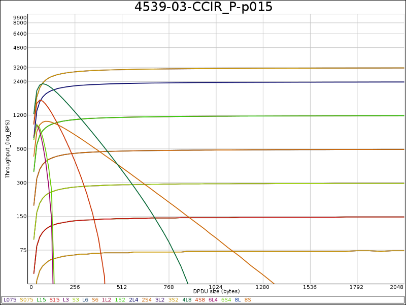
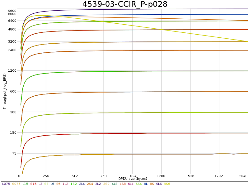
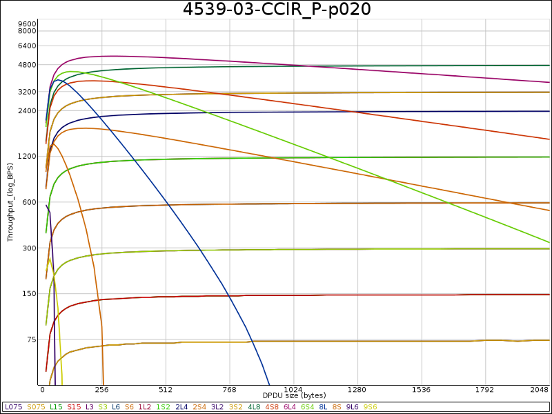
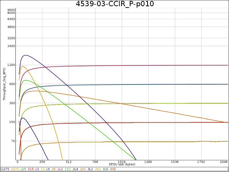
These graphs show four different characteristics. It is clear from looking at these graphs, that there is a transition between them as SNR changes. As conditions deteriorate, the fastest waveforms drop out one by one (with the reverse as conditions improve). These four graph types occur in a cycle, repeating as each wave form drops out (for deteriorating conditions). Because we took snapshots at 1 dB intervals, our graphs occur at various stages in the cycle. The four sample graphs are picked to illustrate clearly each stage. The four graph types are described in the order they would be seen for a cycle (of dropping one waveform) in deteriorating conditions. The number of graphs of each type obtained is noted, which gives some idea of the relative length of each stage of the cycle.
- Flat (2 of 34), with example in Graph 1. Here the best throughput speed with both long and short interleaver converges on the modem speed. This indicates zero frame loss, and so gradual improvement in performance as DPDU size increases. Only one line is seen as two lines (one for each interleaver setting) follow the same curve.
- Flat with tail-off (17 of 34), with example in Graph 2. In this more common variant, the long interleaver converges on the modem speed, but the short interleaver tails off. This reflects slightly deteriorating conditions, which have impacted the short interleaver, but not the long interleaver.
- Broad Peak (11 of 34), with an example in Graph 3. As conditions deteriorate further, the long interleaver curve is also affected. This leads to peak throughput for a medium DPDU size (around 256 in the sample graph) and then tailing off.
- Sharp Peak (4 of 34), with an example in Graph 4. As conditions deteriorate further the peak sharpens. We distinguish a “sharp” peak as one where there throughput has dropped to zero for 1024 byte (max) DPDU size. In the example graph, peak throughput is obtained for a DPDU of around 100 bytes.
- As conditions deteriorate further, the peak will drop below the new “fast” waveform, and it will cycle back to 1 or 2. (For graph 4, it is clear that it will go straight to a graph of type 2).
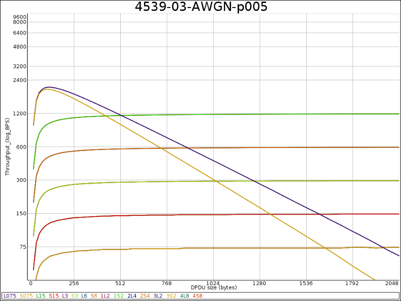
The AWGN graphs, representative of Groundwave conditions, were similar. An example is shown above. In most of the CCIR measurements, performance with long interleaver is significantly superior to short interleaver. With AWGN, the long interleaver gives an improvement, but it was only large in a few cases. The example graphs that shows a typical small improvement for long interleaverl. So for Groundwave communication, long interleaver is still preferable, but does not give the overriding benefit seen for Skywave.
It is useful to consider how the FER-based DRC changing algorithms would work in these conditions. Trinder/Brown and Trinder/Gillespie would both work nicely for Broad Peak (Graph 3 type). They would step up through the waveforms and stabilize on the best performance. It could also work for sharp peak, but may well fail if the DPDU size used is too large (this is likely if a recommended 200-300 byte DPDU size is used).
The more interesting case is the common flat graphs. Here the algorithm would step up to the top graph, and then oscillate between this setting and a faster waveform, lead to sub-optimal performance half of the time. This oscillation is a known defect of these approaches. It is clear from these graphs, that performance will be sub-optimal.
We believe that the AWGN graphs and the characteristics described will reasonably reflect Groundwave transmissions, where SNR variance is expected to be low, and that this analysis is directly applicable.
It is clear from these graphs that intelligent setting of DPDU size is important to gain optimum performance. There are two basic conditions with very different characteristics
- Where best performance is delivered by a “flat” waveform, you will use maximum DPDU size (1024 bytes).
- If best performance is delivered by a “peak”, you will choose a DPDU size appropriate to the peak (typically 100 to 300 bytes) and that the best value for DPDU size can be determined from the FER and current DPDU size.
WBHF Waveforms
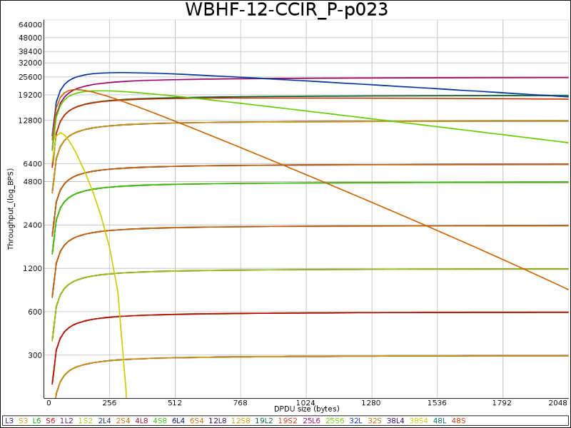
When you move to WBHF, the graphs obtained are very similar. The above graph is a sample from a set for CCIR Poor and 12 kHz channel WBHF. The distribution of graph types was similar to HF:
- Flat: 0
- Flat with tail-off: 18
- Broad Peak: 15
- Sharp Peak: 4
It is clear from these graphs that the standard size range for DPDUs (up to 1024 bytes) for HF remains appropriate for WBHF. This graph shows a setup with optimum DPDU size of around 256 bytes. This generally suggests that WBHF characteristics are similar to Narrowband for low SNR variance.
Intermediate-Term Variation
The Watterson model is used by CCIR and generally accepted as providing accurate simulation of HF channels for short periods (a few seconds). The analysis so far is based on a simulator following the Watterson model.
However, HF Skywave channels vary over longer term. Intermediate-term variation (ITV), deals with variations over seconds to a few minutes. ITV is expected to have significant impact on STANAG 5066, which can have transmissions of up to 127.5 seconds, and needs to predict behaviour at least a few minutes ahead.
The “Walnut Street Model” is the best known paper that covers ITV “The Walnut Street Model of Ionospheric HF Radio Propagation”.
An excellent paper that builds on this is “EMPIRICALLY CHARACTERIZING CHANNEL QUALITY VARIATION ON HF IONOSPHERIC CHANNELS” (William M. Batts, Jr., William N. Furman, and Eric N. Koski – Proceedings of the 2007 Nordic Shortwave Conference). We are not aware of any other (independent) material on ITV.
The ITV literature suggests that variation follows a 4 dB standard deviation with exponential autocorrelation with a time constant of around 10 seconds. We extended our simulation based on 4 dB SNR standard deviation, but assuming a time constant much larger than the interleaver length. This was an attempt to simulate ITV using tools and data available to us.
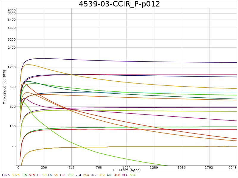
The graphs look quite different to those generated from single SNR value. The best line was generally quite flat, but in most cases rose slightly for small DPDU size, typically giving optimum DPDU size of around 256 bytes. An example is shown above. We analyzed this data in various ways. Our primary conclusion is that we do not trust this data sufficiently to draw any conclusions. It does seem highly likely to us that ITV is going to have a significant effect on performance characteristics, although quite possibly not as much as in the above graph which assumes that the modem will not help much with ITV.
It seems possible that for at least some conditions (e.g.. NVIS were SNR variance is lower (typically 1.7 dB) or for good skywave conditions) that the modem may be effective to at least some extent in dealing with ITV and that the “low SNR variance” analysis of earlier may apply or at least be close to what occurs.
We believe that it is important to make Over The Air (OTA) Skywave measurements, to enable graphs such as the one earlier to be plotted from real data. This will enable us to determine if calculations such as the one made earlier from single SNR data or from channel simulators modelling ITV (such as those developed by Harris) can reasonably be used to represent real world conditions.
It seems that substantial research is needed on ITV characteristics. Given the relative lack of knowledge, a DRC solution needs flexibility to deal with differing conditions and to be enhanced in light of further research.
Determining Optimum DPDU Size
The DPDU is the unit of retransmission. Larger DPDUs have lower overhead, but will have a higher retransmission cost if they are lost. This means that optimal DPDU size will decrease as error rate increases. A graph of BER (Bit Error Rate) against optimal DPDU size is shown below, assuming random error rate. It is only in perfect (or near-perfect) conditions that a maximum size DPDU (1024 bytes) is optimal.
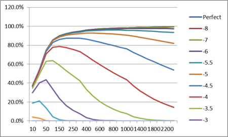
When using STANAG 5066, the application is not generally aware of the BER. In general, it is not possible to determine BER from modern modem protocols and most modems do not supply this information. What is available to the application is FER (Frame Error Rate). Using a simplistic flat-BER model, it is straightforward to map FER and BER, and thus enable calculation of optimum DPDU sizes. We have also found that this mapping can work effectively when allowance is made for error clustering in patterns typical of modern modem output.
For the single SNR graphs, the curves look very much like the theoretical ones here. Where such conditions appear in practice, a simple calculation can be used to determine optimum DPDU size, based on current DPDU size and FER. Under stable conditions where best speed has been determined, one could make a single measurement of DPDU size to determine the best value for subsequent transmissions. It seems likely that this approach will be valid and effective for Groundwave communication.
For Skywave communications, we need to better understand the impact of ITV before any clear recommendations can be made.
Sender Parameter Choice
Key issues relating to transmit speed and DPDU size have been considered in previous sections. This section looks at other parameters and then about putting it all together.
Interleaver
HF interleavers provide protection against Rayleigh Fades. For reliable data transfer, longer interleavers are desirable. “Investigating the Effects of Interleaver Size and FEC Code Constraint Over-the-Air for the US MIL-STD-188-110C Appendix D WBHF Waveforms” makes the case very clearly.
With older waveforms, interleavers gave an overhead due to ramp up and ramp down. Modern interleavers use “tail biting” encodings and so do not have this overhead. To operate without overhead, modem blocks (which are longer for longer interleavers) need to be fully filled. This is discussed below.
At speeds greater than 2400, there is no overhead for a longer interleaver when blocks are fully filled. At 2400 and less, connection synchronization overhead depends on the interleaver. For Long, it is 4.8 seconds, and is 0.6 seconds for Short and Zero. This will need to be taken into account when choosing the interleaver at this speed, and will generally mean that Long interleaver will only be appropriate for longer data transmissions.
In most situations it will be best to use a long interleaver, and in all cases the sender can make “best choice” of interleaver without information from the receiver.
Transmit Length
STANAG 5066 offers a transmit length of up to 127.5 seconds. Because turnaround time can be several seconds (or even tens of seconds) use of long transmit times is important to optimize throughput. However, these long delays can have negative impact on interactive applications like XMPP or Web access. For XMPP you want to enable rapid interchange of messages. This can be considered a good example of an application where you want to optimize for latency. Thales reported (2012 HFIA meeting in York) that Web users were happier with a system tuned for shorter transmit times, as this made the Web pages “more responsive” (even though this tuning increased the overall time to load web pages).
Optimizing for Throughput
Older HF systems are invariably tuned to optimize for throughput. This remains an important target, which will be chosen by the sender for certain types of traffic. We look at how best to achieve this. Consider a situation where data is being transferred, and there is ample data to fill the 127.5 second transmission slot. If optimizing throughput is the primary goal, the following choices will be made:
- Transmit for most of the 127.5 seconds.
- Choose the best speed and DPDU size. This is discussed further below.
- Choose maximum length interleaver.
- Calculate transmission length to fill an exact number of blocks (which is the reason transmission will typically be less than the maximum).
When starting a transmission, the sender may need to guess the best speed and DPDU settings, if there has been no recent transmission to use as a base. The initial ARQ handshake will typically be short, so a conservative value can be chosen. The initial transmission will give the receiver some information, and in particular it should be able to get an initial read on SNR (but not on variance). This will allow the receiver to make estimates based on this, and communicate best speed and DPDU settings to the sender.
As the receiver gets more data, it can measure SNR and SNR variance more accurately and can also measure FER (which the sender can also determine for ARQ data). If the receiver determines that another speed is better, it can communicate this. If the receiver believes that the current speed is best, it can use the FER and SNR data to provide information on best setting for DPDU size.
The receiver may determine that going faster may improve performance. In this situation it can continue to communicate best settings for the current speed, and also provide information to enable the sender to try the higher speed (probe). If the sender tries the higher speed, the receiver can communicate back best setting view in light of the probe. This exchange will prevent Trinder/Gillespie oscillation, while enabling the higher speed to be investigated.
The sender will typically try the higher speed if there is a lot more bulk data to be transferred, but may prefer to stick to the slower (safe) speed if there is only a small amount of data (remaining) to transmit.
Optimizing for Latency
Optimizing for latency is more complex than throughput optimization. There are three basic cases to consider.
Short Messages
Sometimes HF systems will need to transmit only a small amount of data (say 1-2 seconds). Reasons for this might be:
- The data contains only acknowledgements.
- The data is from a protocol like XMPP with only small amounts of data.
In both of these cases, data loss is highly undesirable as it will lead to delays and performance loss due to retransmission. It is straightforward to optimize for this, so the following choices are made:
- Use a speed significantly slower than would be used for optimum throughput, leading to a robust waveform with low risk of data loss. The slowest speed that does not significantly impact transmission time (noting minimum transmit times) is sensible.
- DPDU size is likely to be small, as there is only a little data.
- Choose the largest interleaver that will give a block size that it not too wasteful.
- If there is spare capacity in the modem block, repeat the data. This technique has proved very effective in some STANAG 5066 implementations.
These approaches will significantly reduce the chance of data loss, which will improve protocol performance (for acks) and improve interactivity (for XMPP type protocols).
Large Messages
It may also be desirable to transfer a large message with minimum latency. If this is going to take several minutes at the speed for optimized throughput, it will be sensible to handle (at least the start of) the message as if transmitting for maximum throughput, as the time for data transfer is a significant factor in overall latency. When most of the message has been transferred, “medium message” considerations may apply.
Medium Messages
When the amount to transmit is intermediate, the choices to optimize for latency are less clear cut. If you send faster, it will reduce transmission time, but increase the probability of errors that will lead to retransmission. The delay overhead of retransmission will depend both on the turnaround time, and on the amount of other traffic flowing.
This is a complex trade-off. The approach proposed is to enable the receiver to share information about predicted error rate of transmitting at the rate for optimized throughput and at a number of steps below this. This will provide information to help the sender make “best choice” for the traffic requirements and conditions.
As there is less data, there will be no control over the transmit length. The interleaver will need to be chosen carefully. If a maximum interleaver has a block length of 10 secs, and there is 19 secs of data to send, it makes sense to use this block length (as only one second is wasted). However, if there was 21 seconds of data to send, this block length would be wasteful. It would make more sense to choose a shorter interleaver that will lead to more optimal use, even though this slightly increases the chance of data loss.
We believe that operational experience is needed in order to determine whether a simple approach should be used here, or something more complex.
Mixed Traffic
Sometimes there will be traffic with a mix of requirements. If there is a mix of distinct traffic (e.g., XMPP and email) it may make sense to send only the XMPP traffic, optimizing for latency, and hold back the email traffic for a subsequent transmission when there is no XMPP. This might lead to undue delay of the email traffic if XMPP load is high, so it may make sense to transmit some email traffic along with the XMPP so that progress is made on the email, but to keep transmission time reasonably short to ensure good XMPP turnaround times. It would seem helpful to give some flexibility here, to deal with different customer requirements.
The requirements may be determined by application (e.g., optimize email for throughput and XMPP for low error rate). There could be a case for including QoS data with each of the applications in STANAG 5066 SIS protocol, to enable the STANAG 5066 server to make a better choice.
SNR Measurement Accuracy
The approach taken by Trinder/Brown and Trinder/Gillespie is to start slow and incrementally speed up until FER measurements tell you that speed is optimal. If you can measure SNR accurately, it should be possible to determine optimum speed from SNR and set the best speed from SNR. If SNR measurement is less accurate, then you should at least be able to set a speed fairly close to the optimal speed (ideally slower, rather than faster) and then use the traditional FER-based approach to reach the optimal value. This will avoid stepping through large numbers of speeds that are clearly too slow.
A related issue is the time to get stable SNR. An ARQ transmission will start with a short transmission (part of STANAG 5066 links setup). This transmission will typically be a few seconds. If this is sufficient to get a read on SNR, speed information can be sent to the sender in the ack that follows (as an EOW) so that the sender can switch to a useful speed for the first long transmission. Measurements suggest that for the Rockwell Collins HSM 2050 modems, that a stable value is achieved always in 1 second and usually in 0.5 seconds. This is sufficient to enable SNR based parameter setting immediately.
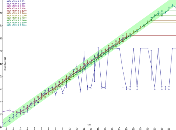
The graph above shows SNR values measured by the modem against the values set in the channel simulator for AWGN. The green bar indicates target. The individual measurements show bars with standard deviation. Apart from 75bps, the measurements appear accurate. This suggests that for Groundwave (AWGN) that SNR measurements are definitely good enough to correctly set the speed (or sometimes a speed slower). It suggests that the probing set out in the next section would be useful for fine tuning.
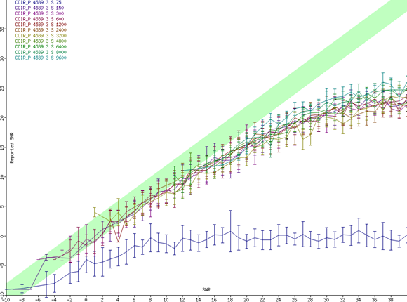
The above graph is the same measurement for CCIR Poor. Here the standard deviation is much larger. There is also a systematic deviation in better SNR conditions, which could be allowed for. It is clear that a reading of a few seconds will not enable accurate setting of the best speed. However, it should enable a “reasonable” speed to be chosen (i.e., to avoid the need to start with a speed that is vastly slower than the optimal one). It may be that measurements of SNR over longer periods can be averaged out to get enable a better speed setting. This needs investigation with OTA tests.
Protocol Proposal
The following proposal is a preliminary protocol suggestion. It is likely to be significantly updated, as experience is gained.
Communication Model
Although the sender has flexibility to make choices for each transmission, the receiver has the best information (e.g., BER, SNR, variation patterns and trends) to take the best view on optimal parameters. So although the sender now has “per message choice”, it still needs information from the receiver to make this choice in the best possible manner. The STANAG 5-66 EOW (Engineering Order Wire) protocol mechanism (and general desire for efficiency) means that this information must be communicated concisely.
The strategy is to communicate three things:
- Best (known/safe) setting to optimize throughput. This will give a recommended speed and DPDU size. Where a previous transmission has been used to transmit at this speed, the error rate is known, and receiver (or sender) can use this to calculate the optimum DPDU size. Receiver can also factor in changing conditions (e.g., stability, variance and trend in SNR) into the calculation. In fairly stable conditions, you would typically expect the speed to stay the same, and DPDU size varied to tune best performance.
- Throughput Probe settings. In some situations, the receiver may know a safe setting for optimizing throughput, but know that there may be a better setting with faster speed and smaller DPDU size. This probe suggests trying sending at the speed above the safe speed. A sender will typically try the probe if there is ongoing “bulk data”, but may elect not to in some situations, for example if it is finishing a transfer. The sender may choose to send a somewhat shorter probe (e.g., 30 seconds instead of 127.5 seconds) in case the probe gives lower performance.
- Information on error rate for the optimized throughput speed and a number of steps below. This allows the receiver to share its best estimates, to enable the sender to optimize choices for traffic with low latency requirements. Typically, traffic optimized for low latency will be low volume, which will make it hard for the receiver to build estimates based on FER. This means that these values will typically be determined from SNR and SNR variance.
Protocol
STANAG 5066 communicates management information use EOW messages. These can be carried with standard PDUs, and so the information can typically be provided without adding any overhead. They can also be sent independently, incurring a very small overhead.
On each transmission, the receiver should update its view of each of the parameters for the sender (the destination of the DPDU), if they have changed since the last transmission made.
EOW messages are 12 bits long, with 4 bits used for the message number. STANAG 5066 has used 8 of the possible 16 message numbers. The following new messages are proposed:
| Message Number | Message |
|---|---|
| 8 | Waveform/Speed for Optimum Throughput |
| 9 | DPDU Size for Optimum Throughput |
| 10 | Throughput Probe |
| 11 | Error Rate Information |
The DPDU size PDU uses all 8 bits, and the optimum size is determined by adding 1 and multiplying this value by 4. (So if the octet is the max value of 255, this represents 1024, which is the maximum DPDU size).
The Waveform PDU is encoded as follows.
| MSB 7 |
6 | 5 | 4 | 3 | 2 | 1 | LSB 0 |
|---|---|---|---|---|---|---|---|
| Speed | Spare | ||||||
The Speed field defines the recommended transmission speed. This encodes the actual speed for standard HF, and the waveform for WBHF (with the speed dependent on channel size).
| Value | Speed |
|---|---|
| 0001-1101 | WBHF. Waveform is the recommended Annex D Waveform number (1-13) |
| 10001 | 75 |
| 10010 | 150 |
| 10011 | 300 |
| 10100 | 600 |
| 10101 | 1200 |
| 10110 | 2400 |
| 10111 | 3200 |
| 11000 | 4800 |
| 11001 | 6400 |
| 11010 | 8000 |
| 11011 | 9600 |
| 11100 | 12800 |
The Throughput Probe PDU is encoded as follows
| MSB 7 |
6 | 5 | 4 | 3 | 2 | 1 | LSB 0 |
|---|---|---|---|---|---|---|---|
| Speed | DPDU Size | ||||||
The Type value has the following meanings:
| Value | Speed (bps) |
|---|---|
| 00 | Do not probe (this overrides a previous probe EOW message) |
| 01 | Probe somewhat unlikely to succeed |
| 10 | Intermediate chance of probe success (or no view on success) |
| 11 | Probe fairly likely to succeed |
DPDU size gives a recommended size to be used in the probe. The value used should be four times the value encoded plus 1. This enables up to 256 to be encoded. Probes are likely to use smaller DPDU sizes, typically 100 bytes.
The error rate information is encoded as follows. Where an FER of zero is indicated for a speed, there is no need to use different PDUs to send FER on slower waveforms.
| MSB 7 |
6 | 5 | 4 | 3 | 2 | 1 | LSB 0 |
|---|---|---|---|---|---|---|---|
| Choice | First FER | Second FER | |||||
The Choice value has the following meanings, to enable FER information to be conveyed on different speed settings.
| Value | Speed (bps) |
|---|---|
| 00 | First FER: refers to optimized transmit speed (OTS) Second FER: refers to one speed below OTS |
| 01 | First FER: refers to two speeds below OTS Second FER: refers to three speeds below OTS |
| 10 | First FER: refers to four speeds below OTS Second FER: refers to five speeds below OTS |
| 11 | First FER: refers to six speeds below OTS Second FER: refers to seven speeds below OTS |
The FER settings are for the speed identified by Choice, and for 256 byte DPDU and Long Interleaver. The sender will be able to make reasonable estimates on the effect of different DPDU size and interleaver.
| Value | FER |
|---|---|
| 000 | 0 |
| 001 | < 1% |
| 010 | 1 – 3% |
| 011 | 3 – 6% |
| 100 | 6 – 10% |
| 101 | 10 – 15% |
| 110 | 15 – 25% |
| 111 | > 25% |
What Next
This paper has suggested some directions in STANAG 5066 DRC and performance optimization. This has led to a proposal that we are confident will work well for Groundwave. More research is needed for Skywave due to ITV.
Next actions include:
- Basic OTA (Over The Air) analysis, in particular to validate some of the ITV simulation undertaken here. Isode’s “HF tool” has capabilities that will facilitate this. The goal is to look at modem output in conjunction with SNR levels and variation (and any other modem provided information on conditions). This data can be analyzed to determine optimal STANAG 5066 performance. We see this as a crucial next step.
- Implementation of the algorithms and EOWs in a STANAG 5066 server, and testing over real and simulated conditions.
- Standardization of a new set of EOW messages, using this research as input.

