Providing TCP Services over HF Radio
TCP (Transmission Control Protocol) is a standardized protocol for streaming services that is used for a vast number of Internet applications and services. This white paper looks at providing TCP Service over HF Radio using STANAG 5066 Annex X: “HF-PEP: TCP Performance Enhancing Proxy Protocol” which in turn is based on the streaming service specified in STANAG 5066 Annex W: “SIS Layer Extension Protocol (SLEP)”.
The white paper starts by looking at the services for which TCP over HF is important, and why this is an important capability. Then it looks at other IP services which are best provided by different mechanisms. The paper then gives a high level summary of how HF-PEP provides TCP services and key design choices. Finally, some measurements are provided.
Key Targets for TCP over HF
TCP is used by a vast ranges of applications and this mapping will allow some of these applications to work usefully over HF, noting that other applications will have application level characteristics (high data volume or high levels of handshaking) that make them unsuitable to operate over HF.
Two families of applications are of particular interest.
- Web Browsing over HF. The key target is not general purpose Web surfing, but to provide a “pull” service to Mobile Units, so they can access websites that provide critical information. This is described in detail in the Isode white paper “Web Browsing over HF Radio”.
- Command and Control (C2) applications of which there are many that run over TCP. Two important ones are:
-
- Tactical Data Link (TDL) using LINK-16 running over TCP using the JREAP-C specification.
- TAK which is a widely used open source C2 system. TAK operation over HF is described in the Isode white paper “Operating TAK over HF Radio”.
Applications and IP Services over HF that are not targets for TCP over HF
TCP over HF is not the right solution for every application. This section looks at applications where different approaches are best, as they provide superior mappings onto STANAG 5066.
Key Applications: Messaging and XMPP
Some mission critical applications define mappings directly onto STANAG 5066. There are a number of options for messaging protocols, as set out in Isode white paper Messaging Protocols for HF Radio. Performance of these protocols can give better than 90% link utilization as described in Isode white paper Measuring Performance of Messaging Protocols for HF Radio
The approach for XMPP is described in Isode white paper Operating XMPP over HF Radio and Constrained Networks. This approach has been demonstrated in UK MoD trials to work well down to 300 bps, with low latency and high reliability.
These optimized protocols obviate the requirement to operate these services using generic capabilities, which would be significantly less efficient.
STANAG 5066 IP Client & Low Volume Applications

STANAG 5066 Annex U specifies “IP Client” which enables operating an IP subnet over HF, as shown in the diagram above. IP Client is suitable for low volume services, in particular:
- UDP (User Datagram Protocol) services, in particular custom military protocols and Domain Name Service (DNS).
- Some ICMP (Internet Control Message Protocol) services, in particular ICMP Ping for status montoring.
IP Client is discussed in detail in the Isode white paper “STANAG 5066 IP Client & Providing IP Services over HF Radio”.
HF-PEP
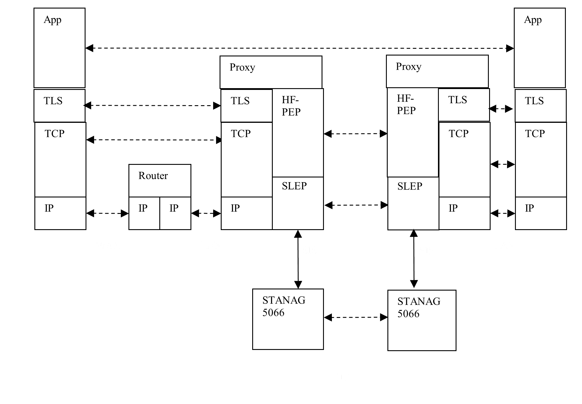
HF-PEP uses a PEP (Performance Enhancing Proxy) architecture, outlined in RFC 3135 “Performance Enhancing Proxies Intended to Mitigate Link-Related Degradations”, to remove the inefficiencies of running TCP over STANAG 5066 IP Client. The overall architecture for using HF-PEP is shown in the following diagram.
In this TCP Proxy architecture, an application is communicating over TCP, running over IP in the normal manner. The TCP connection from each application is peered with a proxy, rather than the other application. The proxies communicate using the HF-PEP protocol specified in STANAG 5066 Annex X: “HF-PEP: TCP Performance Enhancing Proxy Protocol”
HF-PEP operates over SLEP (SIS Layer Extension Protocol), specified in STANAG 5066 Annex W: “SIS Layer Extension Protocol (SLEP)”. SLEP provides the Stream Services used by HF-PEP. SLEP communicates over STANAG 5066, using the local STANAG 5066 SIS (Subnet Interface Service) to connect. STANAG 5066 peers communicate over an HF network, as shown.
SLEP streaming service does most of the work for HF-PEP. It essentially provides a TCP equivalent service, efficiently over STANAG 5066. Notes on SLEP Streaming Service.
- It is based on the STANAG 5066 Unidata ARQ service that is used to transfer data.
- SLEP Streaming Service is designed to be efficient and to have a very small layer overhead.
- The ARQ service is fairly reliable, but sensible STANAG 5066 design choices mean that it is not 100% reliable. The SLEP Streaming Service needs to allow for this to provide reliability in certain situations.
- A SLEP Stream is designed to survive STANAG 5066 CAS-1 link breakages, often caused by ALE link failure. This ensures reliability in very poor conditions.
- SLEP streaming service can multiplex TCP connections over a single HF link, so that a single STANAG 5066 SAP can be shared by multiple TCP connections and multiple applications running over TCP.
HF-PEP is a relatively simple mechanism to create the HF-PEP connection over the underlying SLEP Stream. It passes parameters from initiator to responder, to enable the responder to correctly initiate the second TCP connection. Once this is done, there is no further HF-PEP protocol.
The proxy can manage how various TCP applications are used. Isode’s Icon-PEP product provides a flexible filtering capability that allows selection of traffic based on port, source address (subnet), and destination address. Filters allows various controls.
- Blocking. This might be used to prevent certain types of traffic, such as DNS over TCP.
- Enable or Disable compression.
- Set STANAG 5066 priority. This might allow configuration based on traffic type (Web Browsing vs C2) or source/destination to give priority to certain types of traffic.
Selection of the TLS options discussed next.
TLS PEP

In the basic HF-PEP model, if Transport Layer Security (TLS) is used, it operates end to end and can be considered a part of the application. While this is a clean and secure model, TLS as part of the application presents two performance problems:
- It adds an extra end to end handshake.
- It adds typically about 5 kbytes of data.
Handshaking is always undesirable for HF, and the extra data effectively prevents operation at very low HF speeds.
The solution to this is to provide a TLS PEP as shown in the diagram above. With a TLS PEP, the TLS gets terminated at the proxies along with the TCP. This addresses the performance issues. TLS PEP is specified as a part of STANAG 5066 Annex X, and implemented in Isode’s Icon-PEP product.
As well as eliminating TLS overheads over the air, TLS PEP provides two additional benefits:
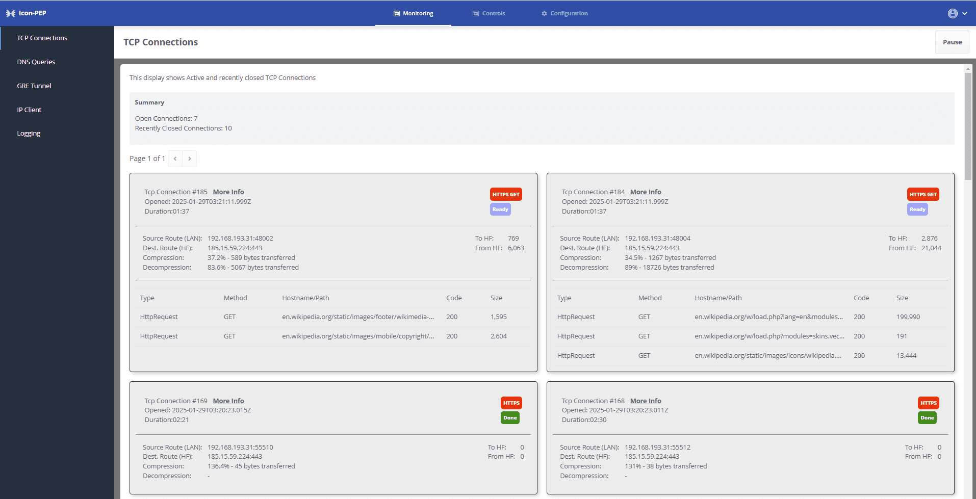
- Because the traffic is unencrypted, it is possible for the operator to usefully monitor traffic. Icon-PEP provides such monitoring capabilities.
- Because the traffic is unencrypted, SLEP compression can be used, which for some types of traffic can usefully improve performance.
TLS PEP introduces some authentication requirements, which are discussed in the next sections.
Server Authentication
TLS provides authentication based on X.509 PKI. A common approach is to have the server present a certificate which is authenticated by the client. This is commonly known as server authentication or one way authentication. This is how security is provided on most web sites.
The TLS initiator will validate the certificate provided by the server in two ways:
- It will ensure that the certificate is issued by a Certification Authority (CA) that the initiator trusts.
- It will ensure that the certificate matches the server using a Subject Alternate Name (SAN) which is typically the domain of the server.
With TLS PEP, this check needs to be supported on both sides. This is how this is achieved:
- On initiator side, the TLS PEP is issued with a certificate that the client will check. For the check to work
- The client needs to be configured with the issuing CA as a Trust Anchor.
- The certificate needs to include the SAN expected by the client. This may mean including a number of SANs in the certificate.
- On HF-PEP responder side, TLS PEP needs to use TLS and check the server certificate.
- The TLS PEP client communicates in the HF-PEP protocol that TLS needs to be used, which will cause the responder to use TLS and make this check.
- The TLS client will set in the SNI (Subject Name Indictor) TLS parameter, the SAN that needs to be checked. This SNI value is passed in HF-PEP protocol, so that the HF-PEP responder can validate the server.
Two Way Authentication
Some TLS systems, such as the TAK protocol noted earlier use two way authentication where both ends validate the peer. When two way authentication is used, there is a need to essentially configure two independent TLS connections, each with strong authentication.
For Icon-PEP a rule is configured on initiator side to match inbound connections by port or address, and a server certificate associated with the rule, as for server authentication. Two way authentication is configured as an additional option, with Trust Anchor information to validate the client certificate. Rules can be added to match one or more client certificates by SAN, which can be domain for a server or email address for a client. Each rule generates an “Auth ID”, which enables multiple independent clients to be configured for an initiator, distinguished by SAN.
The Auth ID is sent over HF-PEP using the encoding specified in Annex X. This enables unique identification of each independent TLS connection with two way authentication.
On the HF-PEP responder side, there is configuration to match each Auth ID, which identifies IP and TLS information to be used in the TLS and TCP connections initiated by the HF-PEP responder.
HF-PEP Protocol

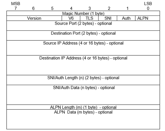
HF-PEP specifies a simple short PDU that is sent at the start of the SLEP stream to communicate key information to the responder. The encoding of this PDU is shown above. Key elements of this:
- Source and destination IP addresses (v4 or v6) and port numbers are specified.
- Use of TLS may be specified.
- Either SNI (for server authentication) or Auth ID (for two way authentication) are encoded.
- ALPN (Application Level Protocol Negotiation) information is encoded, which is needed for some TLS connections.
Measurements
Test Architecture

The above architecture is used to measure performance. Components as follows:
- HF Network simulated by Isode’s MoRaSky tool.
- Icon-5066 (Isode STANAG 5066 product) provides STANAG 5066 service.
- Icon-PEP (Isode Product) provides IP Client and HF-PEP. It connects two IP Routers to provide an IP Subnet service over HF.
- Left Hand Side (LH) router connects to test host.
- Right Hand Side (RH) router connects to test host and Internet.
TCP Measurements are made using a special tool running on each of the test hosts. This tool sends a fixed amount of data and then waits for a short confirmation.
STANAG 4539 emulation was used for speeds of 9600 bps and below. STANAG 5069 with 48 kHz bandwidth was used for the 240 kbps tests. All tests used short interleaver.
TCP Measurements
TCP performance was measured with a special test tool that opens a connection and transfers a specified volume of data to a responding tool, which measures latency throughput (based on time from initial TCP request to all the data being delivered. Data volumes are measured in kilobytes (kB). Data transfers of up to 10 megabytes (MB) were made.
Clear Link Tests
The following tests were made over clear link for varying speeds and data sizes to provide a basic test of HF-PEP for a range of conditions.
|
Speed
|
Size (kB)
|
Utilization
|
Connect Time
|
Total Time
|
Final Data Latency
|
Close Time
|
|
240 kbps
|
1
|
1.8%
|
1.9 secs
|
1.9 secs
|
1.9 secs
|
4 secs
|
|
240 kbps
|
10
|
1.4%
|
2.7 secs
|
11.6 secs
|
11.6 secs
|
4 secs
|
|
240 kbps
|
100
|
25.7%
|
1.9 secs
|
12.9 secs
|
12.9 secs
|
4 secs
|
|
240 kbps
|
1,000
|
73.8%
|
3.4 secs
|
45 secs
|
38 secs
|
8 secs
|
|
240 kbps
|
10,000
|
90.7%
|
5.4 secs
|
367 secs
|
166 secs
|
3 secs
|
|
9600 bps
|
1
|
10.6%
|
7.9 secs
|
7.9 secs
|
7.9 secs
|
7 secs
|
|
9600 bps
|
10
|
29.3%
|
8.2 secs
|
28.4 secs
|
28.4 secs
|
7 secs
|
|
9600 bps
|
100
|
77.2%
|
11.1 secs
|
108 secs
|
108 secs
|
8 secs
|
|
9600 bps
|
1,000
|
90.6%
|
12.9 secs
|
919 secs
|
579 secs
|
7 secs
|
|
9600 bps
|
10,000
|
92.2%
|
10.3 secs
|
9037 secs
|
606 secs
|
7 secs
|
|
1200 bps
|
1
|
67.8%
|
9.8 secs
|
9.8 secs
|
9.8 secs
|
4 secs
|
|
1200 bps
|
10
|
80.9%
|
21.2 secs
|
82.4 secs
|
82.4 secs
|
3 secs
|
|
1200 bps
|
100
|
89.1%
|
17.4 secs
|
748 secs
|
748 secs
|
4 secs
|
|
300 bps
|
1
|
66.7%
|
40.0 secs
|
40.0 secs
|
40.0 secs
|
9 secs
|
|
300 bps
|
10
|
79.1%
|
71.2 secs
|
367 secs
|
367 secs
|
8 secs
|
A number of observations are made on these results:
- The results are good for all speeds and transmission volumes, noting that very short transmissions at higher speeds don’t have time to fully utilize the link.
- As transmissions lengthen, utilization moves towards the link utilization achievable by raw STANAG 5066. This is over 90% at higher speeds, and somewhat less at slower speeds, due to higher STANAG 5066 overhead due to reduced maximum C_PDU segment size.
- Operation was stable for all tests.
- TCP connect time varies somewhat due to STANAG 5066 initialisation timings. In general, this is faster at higher speeds and for smaller volumes of initial TCP data.
- Close time is quite consistent for a given speed. It sometimes takes about double this time, which suggests that detailed timing will sometimes lead to an extra handshake. It is not understood why 1200 bps is so much better than 9600 bps.
- For smaller transmissions, the final latency time is the same as transmission time. This reflects that the sending TCP was able to quickly send all of the data and so all of the data had the same (initial) time stamp. For larger transmissions, the sending TCP buffers data, and so the latency does not grow indefinitely.
Tests with Link Errors
Error rate tests were made at 9600 bps with 100 kB of data transferred, using different Bit Error Rate (BER) values for the link.
| Error Rate | TCP Utilization | STANAG 5066 Utilization | STANAG 5066 Protocol Overhead | STANAG 5066 Turnaround Overhead | STANAG 5066 Gaps & Padding Overhead | STANAG 5066 Data Loss Overhead |
| Clear | 77.2% | 92.1% | 2.6% | 5.3% | 0% | 0% |
| BER 10-6 | 77.1% | 92.1% | 2.6% | 5.3% | 0% | 0% |
| BER 10-5 | 76.1% | 88.6% | 2.5% | 5.3% | 0% | 3.6% |
| BER 10-4 | 40.6% | 55.9% | 5.8% | 5.8% | 0.9% | 34.9% |
The BER range of 10-5 to 10-6 is a typical target for normal operation. BER 10-4 is to illustrate behavior in worse conditions.
The “STANAG 5066 Utilization” column was derived from the Icon-5066 logs for the long data transmission of each measurement. It can be seen that the TCP utilization is well aligned to the STANAG 5066 utilization. The STANAG 5066 overhead is broken into four groups:
- Protocol overhead. This increases slightly when there is data loss.
- This reflects slow HF switching and the need for the reverse transmission to be long enough to minimize risk of the (duplicated) Ack being lost. This is why data transmissions need to be long.
- Gaps due to data loss and completely missing D_PDUs. This is a small impact at the BER 10-4.
- Data loss due to corrupted data. This increases with error rate. BER 10-6 showed no loss in the test run.
These are seen as good results.
Comparison with TCP over IP Client
The following table provides comparative information when using STANAG 5066 IP Client using standard end to end TCP and no HF-PEP. These numbers are provided to demonstrate the performance benefits of HF-PEP. It can be seen that HF-PEP gives much better performance for all settings, and dramatically better for some settings. HF-PEP is not subject to the failures and degradation seen with IP Client. The following measurements are using ARQ.
|
Speed
|
Size (kB)
|
Utilization
|
Connect Time
|
Total Time
|
Final Data Latency
|
|
240 kbps
|
1
|
0.3%
|
11.5 secs
|
11.5 secs
|
0.0 secs
|
|
240 kbps
|
10
|
2.2%
|
6.2 secs
|
14.9 secs
|
8.3 secs
|
|
240 kbps
|
100
|
8.4%
|
12.6 secs
|
39.8 secs
|
9.4 secs
|
|
240 kbps
|
1,000
|
26.6%
|
12.7 secs
|
125 secs
|
64.6 secs
|
|
240 kbps
|
10,000
|
7.2%
|
3.8 secs
|
4660 secs
|
1119 secs
|
|
9600 bps
|
1
|
2.2%
|
37.6 secs
|
38.7 secs
|
4.1 secs
|
|
9600 bps
|
10
|
17.5%
|
26.9 secs
|
47.6 secs
|
24.6 secs
|
|
9600 bps
|
100
|
56.2%
|
22.0 secs
|
148 secs
|
130 secs
|
|
9600 bps
|
1,000
|
80.7%
|
27.9 secs
|
1033 secs
|
566 secs
|
|
9600 bps
|
10,000
|
Failed
|
|||
|
1200 bps
|
1
|
17.2%
|
30.9 secs
|
38.7 secs
|
9.5 secs
|
|
1200 bps
|
10
|
60.3%
|
19.2 secs
|
111 secs
|
95.3 secs
|
|
1200 bps
|
100
|
74.9%
|
19.3 secs
|
890 secs
|
548 secs
|
|
300 bps
|
1
|
32.2%
|
48.7 secs
|
82.9 secs
|
55.1 secs
|
|
300 bps
|
10
|
39.4%
|
110 secs
|
677 secs
|
603 secs
|
Non-ARQ measurements
The following table is the ARQ results at 9600 bps, extracted from the earlier table for convenient comparison with the following table.
|
Size (kB)
|
Utilization
|
Connect Time
|
Total Time
|
Final Data Latency
|
|
1
|
2.2%
|
37.6 secs
|
38.7 secs
|
4.1 secs
|
|
10
|
17.5%
|
26.9 secs
|
47.6 secs
|
24.6 secs
|
|
100
|
56.2%
|
22.0 secs
|
148 secs
|
130 secs
|
|
1,000
|
80.7%
|
27.9 secs
|
1033 secs
|
566 secs
|
The following table shows Non-ARQ results at 9600 bps.
|
Size (kB)
|
Utilization
|
Connect Time
|
Total Time
|
Final Data Latency
|
|
1
|
5.8%
|
13.4 secs
|
14.5 secs
|
4.1 secs
|
|
10
|
19.3%
|
20.5 secs
|
43.1 secs
|
26.7 secs
|
|
100
|
56.3%
|
20.0 secs
|
148 secs
|
60.9 secs
|
|
1,000
|
79.3%
|
16.1 secs
|
1051 secs
|
629 secs
|
Notes:
- Non-ARQ performance over a clear link is similar to ARQ performance.
- Faster TCP connect with non-ARQ leads to somewhat better non-ARQ throughput for small volumes.
- ARQ turnaround times are lower than non-ARQ (controlled in the test by STANAG 5066 Annex K CSMA with slotted configuration). This leads to relative ARQ performance improvements for higher volumes.
Tests with Link Errors
Error rate tests were made at 9600 bps with 100 KiB of data transferred, using different BER values for the link.
|
Error Rate
|
ARQ Utilization (in order)
|
ARQ Utilization (any order)
|
Non-ARQ Utilization
|
STANAG 5066 ARQ Utilization
|
|
Clear
|
56.2%
|
58.4%
|
56.3%
|
93%
|
|
BER 10-6
|
53.9%
|
57.6%
|
46.6%
|
91%
|
|
BER 10-5
|
40.0%
|
44.7%
|
34.9%
|
70%
|
|
BER 10-4
|
24.7%
|
23.6%
|
Not viable
|
50%
|
Notes:
- The TCP connect time is highly variable (10-40 seconds) and this has a significant impact on the exact throughput numbers.
- ARQ utilization changes broadly in line with underlying STANAG 5066 link utilization. This reflects that STANAG 5066 ARQ is providing reliability, and TCP behaviour remains unchanged.
- Non-ARQ performance falls off more rapidly. Non-ARQ does not provide reliability, and so reliability is provided by the TCP mechanisms. These are not optimized for HF, so do not work so well.
- The TCP reliability mechanisms failed completely for BER of 10-4
- Tests for ARQ were done with “in order” selected and not selected. We had anticipated that this value would make little difference, but it appears that better results are obtained when “in order” is not selected
These measurements suggest clearly that use of ARQ is going to be the best approach for TCP over IP Client, as it deals better with HF errors than non-ARQ.
This data is included primarily for comparison purposes and to make clear that HF-PEP is the right approach for TCP.
Icon-PEP
Icon-PEP is Isode’s product that supports HF-PEP. Details here.
Key features include:
- Support of HF-PEP
- Support of TLS Proxy
- Support of IP Client
- Flexible rules to block, configure and prioritize traffic
- Enable/Disable, so that traffic can be turned off in very poor conditions
- Monitoring of TCP traffic, shown below

Conclusions
This paper has shown the HF-PEP is an effective way to support TCP connections over HF, and that optimal use is made of the HF link using STANAG 5066 for a wide range of transmission speeds and transfer sizes in a manner resilient to HF errors. It also shows how TLS can be supported using TLS Proxy.
This is an important HF application capability, particularly to support Web browsing from Mobile Units and C2 communication over HF.

