Automating use of HF Directional Antennae for Mobile Unit Support with ALE and STANAG 5066
HF Directional Antennae can provide significantly better performance than omni-directional antennae. To use a Directional Antenna in support of a Mobile Unit (MU) it is important to correctly point a shore Antenna at the MU and to track its movement. This white paper explores what is needed to achieve this, both for the simple case where an antenna is dedicated to an MU and in various scenarios where Antennae are shared. The paper considers how supporting this plays into Isode’s product architecture and in particular with the Icon-5066 and Red/Black products. It looks at how the product set could be enhanced to support the capabilities outlined in this paper.
Using HF Directional Antennae
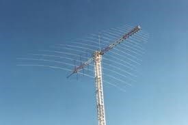
HF Antennae, such as the rotate-able Dipole Antenna shown above can adjust azimuth and sometimes elevation to provide optimized performance for a specific target area
In principle, an MU could use a directional antenna, but in practices this is impractical and so they will usually use omni-directional antennae, For this reason, this paper focused on asymmetrical scenarios where directional antennae on shore are being pointed at MUs with omnidirectional antennae. If needed, the models in this paper could be easily adapted to MUs with directional antennae.
When communicating with MUs over skywave, it is generally desirable to have 1:1 communication. Skywave is hard enough without attempting to handle multiple MUs at once. Also it will generally be impractical to set direction for more than one MU. For a modern system, this will mean:
- Use of ALE to select best frequency; and
- Use of ALE 1:1 mode in STANAG 5066 Ed4 to provide link level service.
Broadcast and a BRASS type service can be a helpful complement to 1:1 communication. This paper looks at how directional antennae can be used to enhance the associated ship to shore communication. Multicast operation using protocols such as ACP 142 are seen as best for more robust surface wave scenarios, such as Naval task group support.
Typical shore deployments will have independent transmit and receive sites. This means that you would ideally use two directional antennae, one for transmit and one for receive. Clearly both antennae would need to be pointed at the target MU.
Directional Antenna Characteristics
A typical log-periodic directional HF antenna has a beam width of about 60 degrees. This means that the requirement is to point the antenna in the right general direction, not precisely at a MU. Precise pointing might be undesirable, as it could facilitate a third party to identify MU location. This is the type of antenna primarily considered here.
An alternative to moving a single antenna is to have a set of directional antennae that together provide full coverage. Then call handling can simply select the antenna with the right coverage, which will be faster than moving a single antenna. This selection model can be easily used with the techniques discussed later.
Some antennae arrays provide narrower beams, which is generally handled at the antenna level and narrowing once signal is detected. This technique can also be used to null out interferers. Sophisticated array antennae can also be used to detect which direction a signal is being received from and automatically configure to adapt. This is described in paper “An alternative approach to HF receiver architectures” by Arnie Johannsen presented at Nordic HF 22.
Control at STANAG 5066 Layer
This paper is primarily considering approaches for data rather than voice. Modern applications all use STANAG 5066 and STANAG 5066 enables multiple applications to share a link by multiplexing traffic. Control at the STANAG 5066 layer is preferable to control at application level, as this control can be shared by all applications.
The modem layer is too low to conrol direction on transmission, as it has no knowledge of destination. Control could be done at the ALE layer, but Isode provides the Icon-5066 server which is ALE unit independent, so working at the higher layer gives an approach which is ALE unit independent. Working at the STANAG 5066 layer has other benefits:
- It fits well with the proposed MU location mechanism
- It supports moving the antennae before attempting to link
Shore Link Dedicated to MU
The simplest scenario is where there is a shore system dedicated to a single MU. Here, the antennae (transmit and receive pair) can be oriented for a single MU, and just track its movements, This is functionally clear and will typically need gradual antenna movement (faster for a plane than a ship). Given the broad beam of a typical directional antenna and typical HF distances, this tracking will happen over hours or days to keep the antennae aligned. This is a slow process to keep the antennae aligned, not detailed alignment during a call.
Functionally, you need to know where the MU is and then use this information to adjust the antennae being used on shore to communicate with the MU. The details of this are considered in the next sections.
Locating the MU
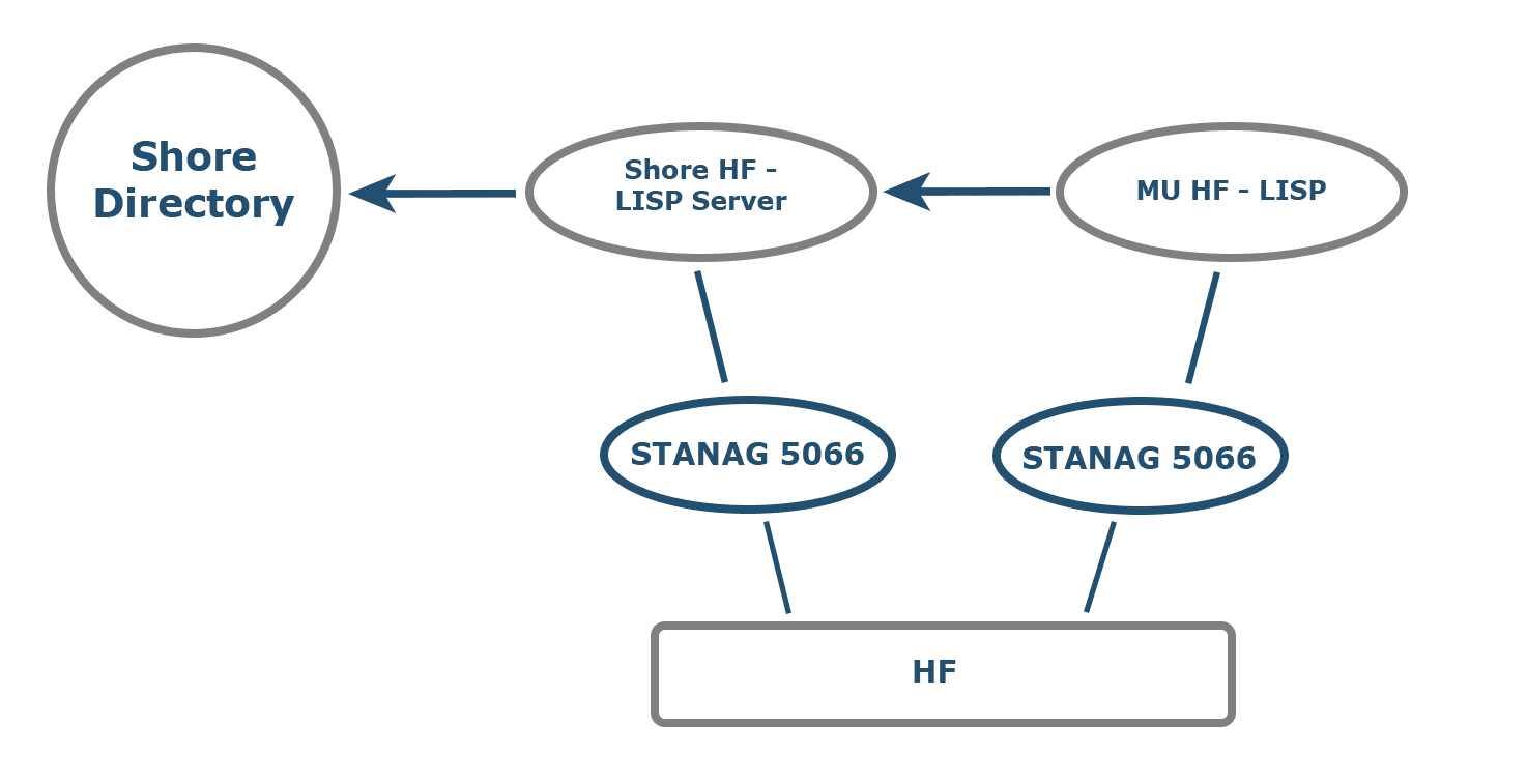
There are a number of systems for tracking MUs which could potentially be employed. Some HF protocols are modem-level (black side) which present security issues. Isode has proposed a secure HF Approach in HF Location & Information Sharing Protocol – HF-LISP (S5066-APP10). This allows mobile units to efficiently share information over STANAG 5066, in particular location and direction/speed of travel. This means that the location can be determined exactly when an update reaches shore and location at subsequent times predicted.
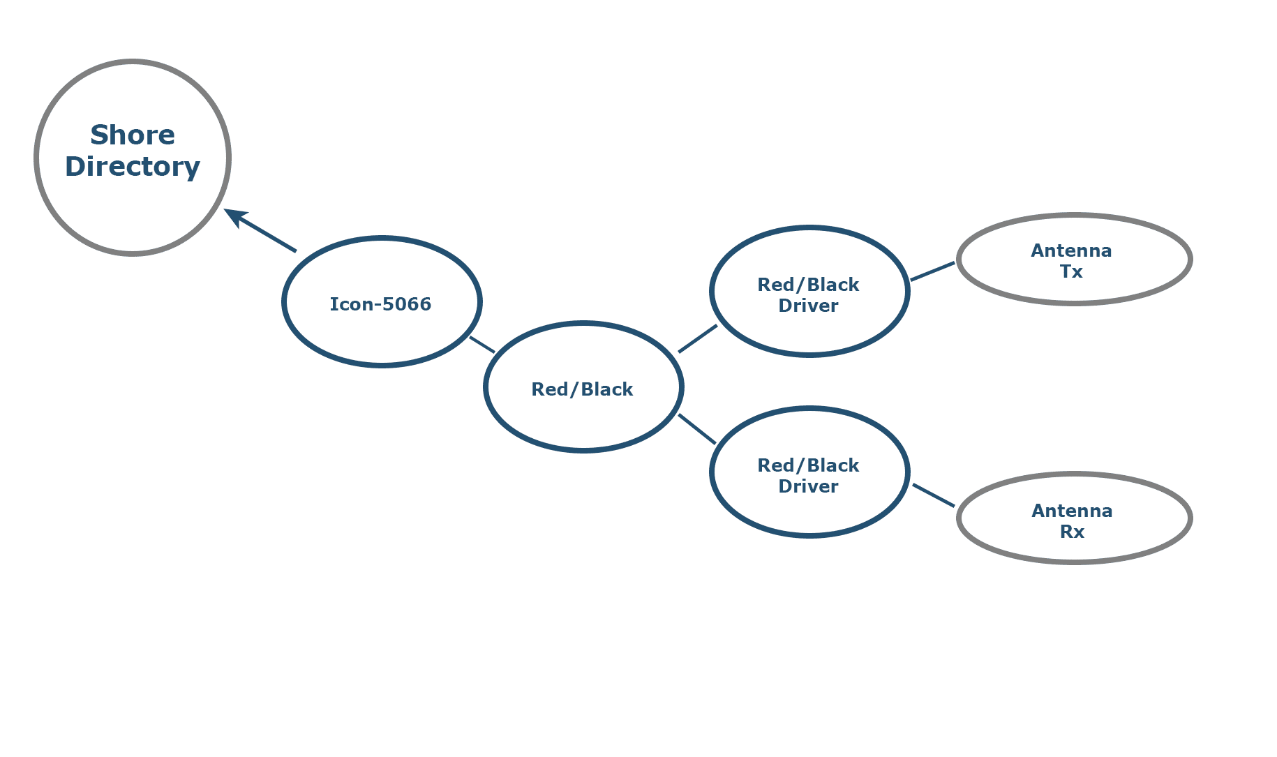
HF-LISP service will operate to keep information on MU location in a shore-side directory, so that MU location information is locally available to processes controlling antennae. The above diagram shows how location information flows from an MU to the shore directory service where it can be generally accessed.
Controlling the Antennae
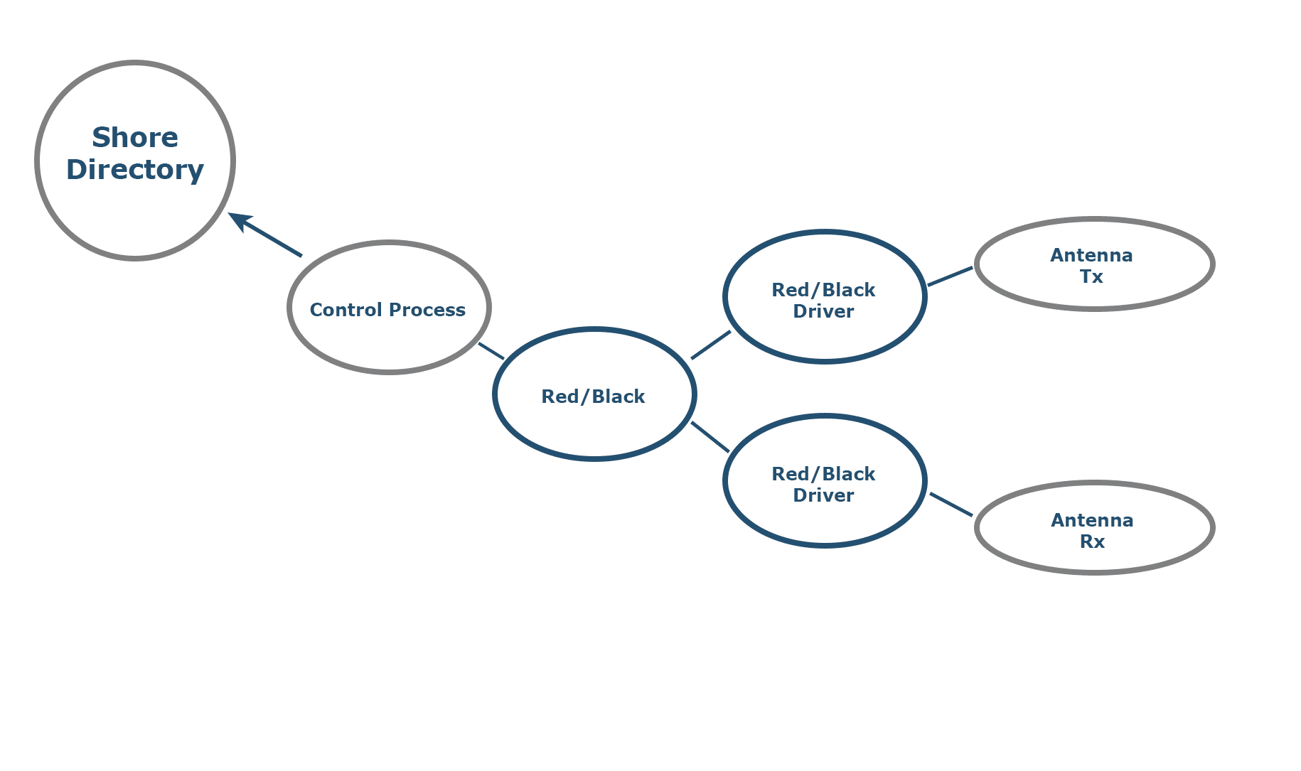
Directional Antennae products will provide management interfaces to control azimuth and (sometimes) elevation of the antenna. Isode’s Red/Black product provides operator management and control of devices in the HF communications chain. This communications chain management will be used to support more complex configurations described later.
Red/Black has a model of device drivers, which enables the operator to work with an abstract representation of the device, with the device driver mapping the abstract specification to the specific device details. This can give a helpful operator view, but also provides a means to provide a common interface to different directional antenna products.
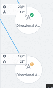
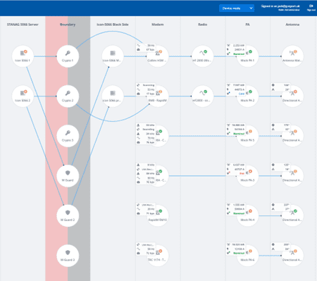
The Http/Json interface used by the Red/Black Web UI can also be used by other programs to control and monitor devices. This will enable an antenna control program to read location of an MU from directory on shore and then control one or two antennae to correctly point to the MU. The Red/Black operator can monitor settings for each antenna, with the Red/Black UI shown above.
Knowing Which Antennae to Move
The control process above can move antennae to point to the location of a given MU. In a typical shore system there will be many applications and many antennae. A STANAG 5066 server will know when it is connected to (or about to connect to) a given MU. Thus it makes sense for the STANAG 5066 server to be driving control of the antennae, particularly to move antennae prior to making a connection.
A STANAG 5066 server will be connected indirectly to the antennae, which might include a chain of devices, potentially including: Modem; Radio; Power Amplifier; Antenna Switch. A typical site will be using switches to flexibly move around connections and so the antennae associated with a STANAG 5066 server varies.
Isode’s Red/Black process manages the communications chain, as shown above, and so is aware of device connectivity. So the control process can use this connectivity information to determine which antennae to move.
Sharing Antennae: Shore Initiated Links
It is not always possible to dedicate separate antennae for each MU. This section considers what is needed to share antennae when connections are initiated from the shore. When a connection is made to a new MU, the sensible approach is to move the antennae correctly before initiating the connection. When MUs share antennae, there may be a need for considerable antenna movement before switching between MUs.
This control is done by Icon-5066 prior to requesting an ALE link:
- Using information from Red/Black to determine which antennae need to be moved.
- Using information from the MU stored in the shore directory to work out where to point the antennae.
- Using Red/Black to control the antennae.
Using a Pool of Antennae
The approach described so far will work for a single Icon-5066 server, or for multiple Icon-5066 servers each with an assigned set of MUs. This can work because application level routing for MUs in products like Isode’s M-Link and M-Switch will be configured to route a given MU to the right Icon-5066 server.
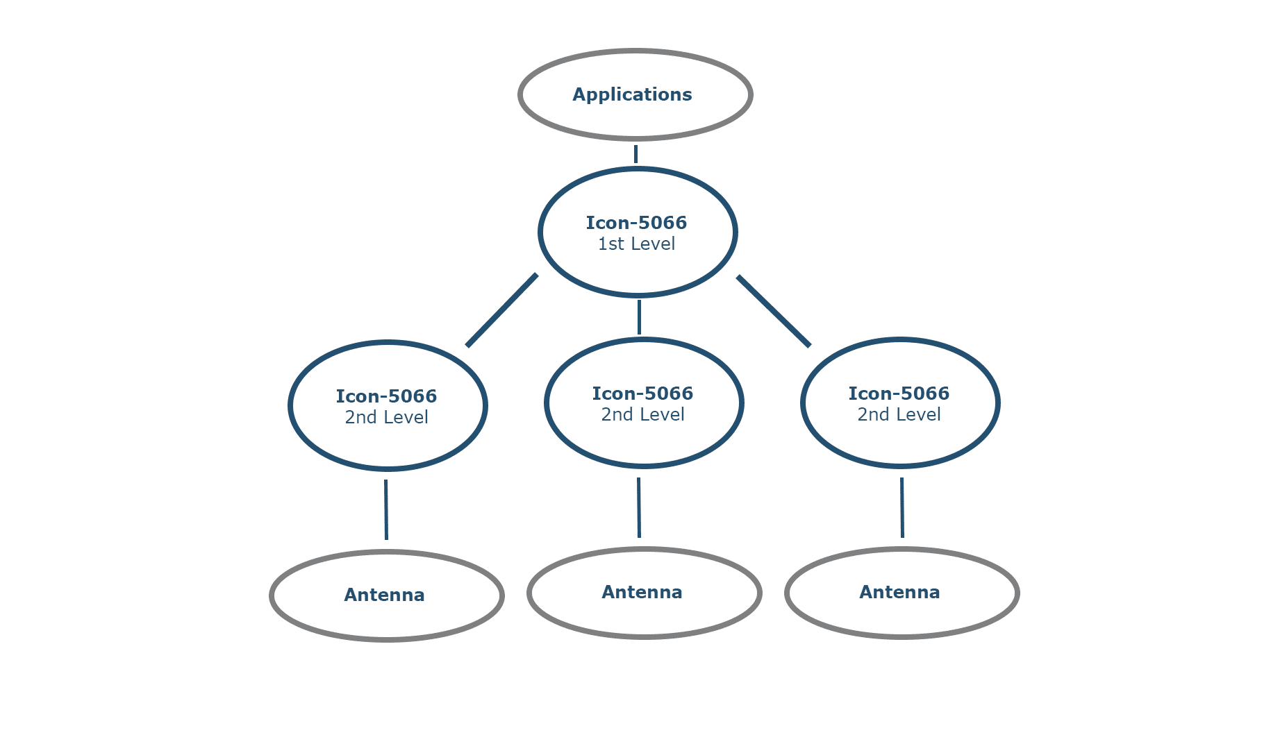
It would be attractive to support a pool of antennae that could be used for any MU, as assigning MUs to servers is expected to be sub-optimal. To achieve this, a hierarchy of servers is used, with the approach outlined in STANAG 5066 Ed4 use of ALE 1:1. Applications need to connect to a single STANAG 5066 server, so that MU routing is transparent to the application. There is a set of second level servers – each with an associated antenna pair. Each of these second level servers will operate a single ALE link. When there is a need for a new ALE link the top level server will route traffic to a second level server which does not have an active ALE link. As in the simple scenario, each second level server will set direction of the associated antennae prior to initiating ALE linking.
Sharing Antennae: MU Initiated Links
This section looks at the approach taken for MU initiated connections. Where the MU initiates the connection, it is possible for the receiving antenna system to detect MU location. The focus here is on application level control.
ACP 127 FAB Approach
The BRASS system historically used “direct to modem” ship to shore links with single receive antenna. The FAB (Frequency Assignment Broadcast) system allows a ship operator to manually select a frequency that will connect to shore. The initial RATT Call Message sent by the operator identifies the ship and the sector (location) of the ship.
The operational expectation is that initial reception will be done with an omnidirectional antenna. When the ship location is identified, a directional antenna pointing at the ship will be switched in, giving improved performance for the call. The FAB protocol can be used to ensure that messages are not sent until the antenna is correctly assigned and directed.
Supporting ALE and Modern Protocols
Where there is not a dedicated link, it makes sense for shore systems to listen on an omnidirectional antenna. Once an ALE link is established, shore system will know the identity of the MU. It’s approximate location will likely be known; if not it can be determined using HF-LISP.
Once the location is known, a pair of antennae can be pointed at the MU, and then these can be switched in by the shore Icon-5066 server to replace the omnidirectional antenna. The shore system can time this switch between receiving and transmitting data, so that it should not impact ongoing data exchange.
Use of Antennae Pool
The system described can be used with a single receiver or with a set of MUs assigned to each of multiple receivers. As with transmission, this is sub-optimal.
To support a pool of antennae providing service to multiple MUs a mechanism needs to be provided that will enable all receivers to share a single ALE address. Two approaches are noted:
- The ALE Units can co-ordinate for multiple receivers, so that only one will answer an incoming ALE call. One ALE product does this, but it is not a general capability
- Extend Icon-5066 to co-ordinate between servers and have only one server scan for a given ALE address. Once that server accepts a link, then another server will start to scan.
Conclusions
This white paper has described how automatic handling of directional antennae could be provided to support shore/MU communication. It has explained how the Isode HF product set could be extended to support this. Isode is keen to work with partners on this capability.
Whitepaper Licensing
Isode whitepapers are licensed under a Creative Commons Attribution-ShareAlike 4.0 International License
![]()
Browse Related Whitepapers
